Thank you so much for your involvement with the Owner's Club Forum! We hope you've gotten some great information and had the chance to interact with other owners on the current system.
Operating a bow mounted trolling motor from a remote location.

Seemann
Member Posts: 11 ✭
I have a MotorGuide Pro 75 trolling motor mounted on the bow of my Hurricane FB196 O/B which is configured for fishing. Because the trolling motor is rather large it is mounted at an angle on the forward deck. This precludes me from using my second seat on the bow unless I take it on and off when raising or lowering the trolling motor. The motor is controlled by a 5 speed foot pedal which is mounted to the deck. Since I like to troll using planer boards I find it impossible to do it alone, meaning I need someone seated on the bow to operate the motor. I would like to operate it from my steering console which is slightly aft of midship, and on the starboard side. My MotorGuide Manual showed a 16' Foot pedal extension cable as an accessory, but alas, they have discontinued it. That cable would have allowed me to operate from the console when trolling, and from the bow when baitcasting. MercMarine discouraged trying to jury rig something that may interfere with the proper performance of the motor.
Not to be deterred, I thought why not leave the foot pedal where it is, and provide a heavy duty cable, connected to a steering quadrant of some type, that would simply raise and lower one end of the foot pedal. A benefit of that would be the ability to lock the motor in any position, mostly straight forward. Right now, if I remove my foot from the pedal the motor turns right because of the rotation of the prop. The pedal has a momentary switch at the side, when depressed runs the motor at a preselected speed, usually 1. Foot off/motor stops. A similar cable setup could be arranged for the speed control. The foot pedal also has a 3 position switch that would allow the motor to run constantly, but then I'd have to run up to the bow to turn it off. A simple accessory would solve my problem, but it is no longer available. No after market part either. If anyone has an alternate suggestion to control this motor from both locations I would appreciate your comments. And, NO! I am not buying a new digital remote trolling motor.
Not to be deterred, I thought why not leave the foot pedal where it is, and provide a heavy duty cable, connected to a steering quadrant of some type, that would simply raise and lower one end of the foot pedal. A benefit of that would be the ability to lock the motor in any position, mostly straight forward. Right now, if I remove my foot from the pedal the motor turns right because of the rotation of the prop. The pedal has a momentary switch at the side, when depressed runs the motor at a preselected speed, usually 1. Foot off/motor stops. A similar cable setup could be arranged for the speed control. The foot pedal also has a 3 position switch that would allow the motor to run constantly, but then I'd have to run up to the bow to turn it off. A simple accessory would solve my problem, but it is no longer available. No after market part either. If anyone has an alternate suggestion to control this motor from both locations I would appreciate your comments. And, NO! I am not buying a new digital remote trolling motor.
Comments
-
The manufacturer does not have any accessory cables that would allow me to extend the foot pedal to a remote location, so I will have to leave it where it is. I have to go down to the boat to get some measurements, namely, the distance between the upper and lower limits of the foot pedal. I'm thinking I could mount a large bicycle sprocket next to the foot pedal, put a pin thru the sprocket into a hole or socket on the pedal at the same radius as the foot pedal hinge pin. A piece of bicycle chain attached to 2 stainless steel cables connected to a quadrant should allow me to pull the sprocket in either direction thereby raising or lowering the pedal. The pin could be spring loaded, or removable to allow use of the pedal without attachment to the remote cables. A spring in the cable would take up any slack so movement would be positive pull/pull.
I also need a way to depress the momentary switch that won't interfere with normal use of the pedal, to turn the motor on and off.
An alternative to the cables would be a more rigid, single cable, like a steering cable, attached to a scissor type device that would raise and lower the pedal. Perhaps a spring loaded pipe with a slot and a wedge shaped sail that would go under the pedal to raise it. Still need a good way to get the pedal back down, Another pipe, or a double action pipe? A wedge alongside the pedal with an angled slot. A pin on the pedal would rise and fall with the wedge movement. Has anyone invented the wheel yet?
-
I'm gradually coming to a conclusion. I have all these ideas spinning around in my head, but the simplest solution seems to be to remove the foot pedal hinge pin, and replace it with a longer one. The pin is not bound to either the pedal or the base, so if I drill a hole midway through the pin, under the pedal, and insert a 3-4" pin it would move the pedal when the pin is rotated. The pedal moves freely by hand so a small bicycle sprocket fastened to the pin would be sufficient to turn it. The sprocket would then be turned by a length of bicycle chain connected to either 2 cables and a quadrant (pull/pull), or a single cable with a return spring connected to a quadrant at the console. The cables would run thru a conduit to the quadrant. The sprocket could have a thru pin, or thumbscrew to lock it to the hinge pin when operating remotely, or loose when operating at the bow position. I like it! Now, I need to figure out how to depress the momentary switch, or rewire the Constant On switch with a simple toggle switch on the console.
-
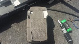
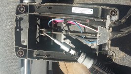
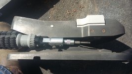
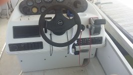
Okay, I have been over engineering this problem in my head. This morning I went down to the boat and removed the 4 screws holding the foot pedal to the deck. When I turned it over I saw that the upper movable pedal had a triangular piece molded into it. At the apex was a 3/16"stainless steel pin connecting the pedal to the push/pull cable that rotated the motor shaft by a rack and pinion assembly in the head. All I need to do is to connect "MY" cable from the console to this same pin. Unfortunately, there is not enough room, the cable takes up most of the space. However, I can remove the pin which is 0.900" long, and replace it with a longer pin which will protrude outside the apex. I have taken a few pics that show: 1. the foot pedal; 2. the underside of the foot pedal (screwdriver pointing to apex pin); 3. the momentary switch (micro switch); and 4. my console. Sitting at the console I determined the most comfortable site for the control box quadrant would be on the right side at the lower rail. The pic of the foot pedal shows the pedal which seesaws forward and back. The momentary switch is at the upper right and controls the speed. The other 2 switches are speed selection.
Steering problem has been solved. A 10' control cable will reach from the foot pedal to the console. How do I turn the motor on and off without depressing the momentary switch? That switch is a micro switch. Step on it and the circuit is closed. Release it and the circuit is open. There are 2 wires connected to the micro switch. By removing them, and adding Crimp-On Quick Disconnects (available a Radio Shack) I can now connect 2 wires to each terminal. The 2 original so the foot pedal works at the bow seat, and 2 new wires that go to a SPST toggle switch at the console. By closing the switch at the console I complete the circuit just as if I had stepped on the switch.
SO, ANYONE WHO HAS A CABLE TYPE FOOT PEDAL TO RUN THEIR TROLLING MOTOR NOW HAS THE ALTERNATIVE TO OPERATE IT REMOTELY FROM ANOTHER PLACE ON THE BOAT!
-
Sorry, I accidently hit POST. I wanted to say that different manufacturers may have slightly different designs, but you can get a Parts diagram, and Wiring diagram to help you. I didn't get a chance to post my pics above so I'll post them here. I'll take more pics when I finish the project and let you know how it works. Sorry the post is so lengthy, but I never could write what I wanted in 30 words or less.
-
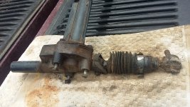
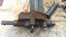
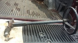
Sailing along! I found something in my shop a few days ago that I think I can use in place of a Control Box Quadrant, which are very expensive. It's an old lawn tractor steering column with a Rack & Pinion system. After removing the steering knuckle from the pinion it appears to be a 3/8: NF thread on the end. I can make a cable end fitting for that. The steering column shaft would have to be cut down to within an inch or two of the steering box to fit alongside my seat, on the bulkhead, and about inline with my Steering Control Box. See Console pic. When mounted the rack would move left when the wheel is turned left. That would push the cable at the Foot Pedal Pivot Point away causing the motor to turn to the right. Backwards! I'll need a simple see-saw pivot to change cable direction. I'm attaching a few pics so you can see what I'm talking about. I'll need to replace the steering wheel with a smaller, flat wheel to get it as close to the side of the bulkhead as possible. I may use an old 10" circular saw blade as the center spoke and rim, then laminate a wood grip onto it.
-
Since this is a foot pedal cable operated system I'm going to stick with a mechanical steering cable system. The rack and pinion steering column I have was made by The Kerch Corp. in Wisconsin. It is a very sturdy unit. I disassembled the gearbox and discovered it is a planetary gear system, not a simple rack and pinion as in the trolling motor head. I contacted The Kerch Corp., but unfortunately they have not responded. I have been trying, unsuccessfully so far, to remove the steering wheel from one end of the column, and a hollow spur gear at the other. Neither will budge. I have the retaining nut off the steering wheel, and can finally see grooves around the shaft. When I go back to the farm I'll retrieve a puller, some lubricant, and make a large split washer to fit behind the steering wheel so the puller teeth will not damage the plastic hub. The spur gear is wobbly, but will not come off. It must be attached some way that is hidden by the 1 1/2" column. I cannot see any pin, spring washer, or screw to remove the gear from the outside, So, progress is slow, but I'll get it apart and modify it. I'll need about a 9 or 10' cable, and one of those right angle metal extension rods to change the direction of cable pull so that a left turn of my steering wheel is a left turn for the motor. The story continues.